Surface roughness is one of the few numbers that can decide whether an optical component performs as designed or silently loses light at every interface. In optical polishing, surface roughness is the average height of the microscopic peaks and valleys left on a part after machining and finishing, and it directly controls how light is transmitted, reflected, and scattered. For engineers specifying precision optics, understanding this single parameter is often the difference between a component that meets spec and one that introduces stray light, haze, or signal loss in the field.
For procurement and engineering teams, roughness is also a commercial lever. Tightening it without a reason raises cost and lead time; leaving it loose on a functional surface risks field failure and returns. The aim is to specify the lowest roughness that meets the optical requirement economically, which is exactly the conversation a good polishing partner should help you have.
This guide explains what surface roughness means in practice, how it affects optical performance, where it becomes a real purchasing decision, and how to specify it so your supplier returns a part that is right rather than merely shiny.
What Surface Roughness Actually Measures
Surface roughness describes the tiny, repetitive deviations from a perfectly flat or curved surface. After grinding or milling, a part may look smooth to the eye yet still carry scratches and grooves measured in micrometers or nanometers. Polishing exists to reduce those deviations to a level where they no longer disturb the optical function.
Ra vs RMS: Two Ways to Read the Same Surface
The two values you will see most often on optical drawings are Ra and RMS.
- Ra, arithmetical mean roughness, averages the absolute deviation from the mean line over a measured length. It is the most common calling value and easy to compare across suppliers.
- RMS, root mean square roughness, squares the deviations before averaging, which gives more weight to occasional deeper scratches and spikes.
For the same surface, RMS is typically about 1.1 to 1.25 times the Ra value, so comparing one supplier’s Ra against another supplier’s RMS without conversion is a common and costly mistake. Most optical specs quote Ra in nanometers; precision polished surfaces often fall in the low-nanometer or sub-nanometer range.
Why Nanometer-Scale Numbers Matter for Optics
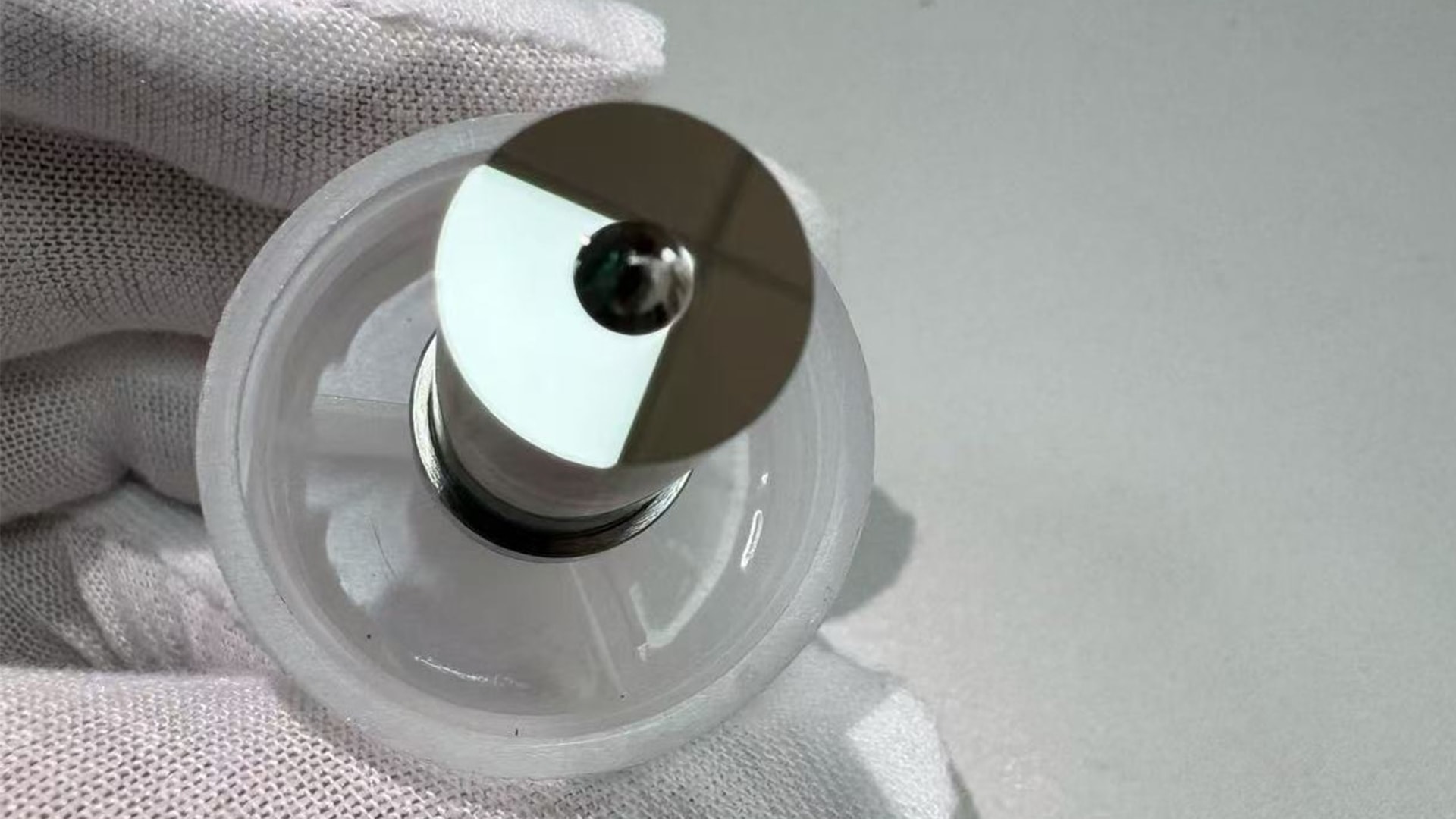
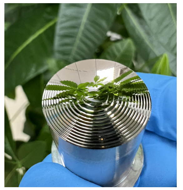
Light does not care what a surface looks like to the naked eye. A scratch only a few tens of nanometers deep can still scatter visible light and especially short-wavelength light. When surface roughness drops below roughly Ra 1 nm, the surface begins to behave more like an optical mirror than a machined part, with scattering falling sharply as roughness decreases. This is why high-end optical polishing is discussed in nanometers, not micrometers.
How Surface Roughness Affects Optical Performance
The practical effects of roughness show up in four related ways:
- Transmission loss: micro-scratches act like tiny apertures that diffract and absorb part of the beam.
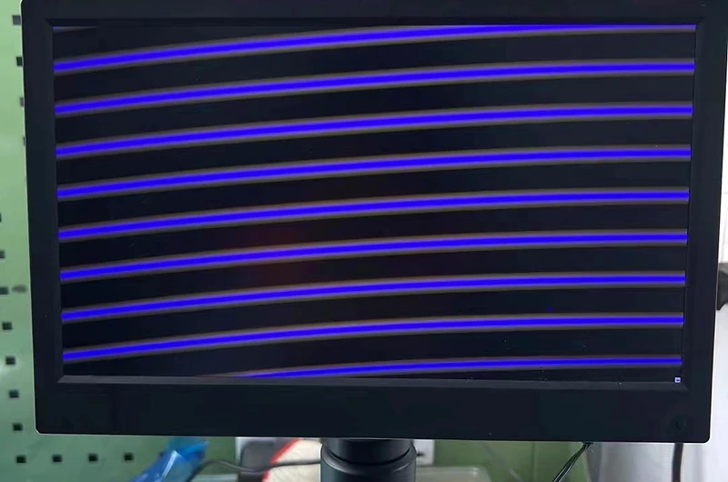
- Scattered light and haze: rougher surfaces spread a fraction of light into unwanted angles, lowering image contrast and raising background noise.
- Reflection control: for reflective optics, roughness determines whether the reflection stays specular or becomes diffuse.
- Laser stability: in laser components, surface flaws concentrate the field and can become premature failure points.
As a rule of thumb, the rougher the surface, the more light is redirected away from the intended path. The table below maps typical Ra ranges to expected behavior.
| Typical Ra range | What you can expect | Common use |
|---|---|---|
| Ra 0.05 to 0.5 µm, machined or ground | Visible texture, strong scattering, diffuse reflection | Structural or non-optical faces |
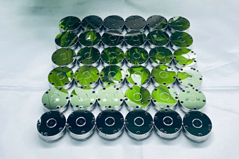
| Ra 1 to 10 nm, fine polished | Low scattering, good specular reflection | General optics, molds, lenses |
| Ra below 1 nm, precision optical polished | Near-mirror, minimal scattering | Laser, imaging, high-NA optics |
Surface Roughness in Real Optical Applications
The same Ra number means different things in different products. A useful way to think about the requirement is to start from the application, not from a generic smoothness goal.
Laser and High-Power Optics
In laser windows, lenses, and mirrors, even sub-nanometer residues of roughness can concentrate the beam and trigger damage or scatter that reduces delivered power. Here the roughness target is usually the tightest, and verification matters as much as the process.
Imaging, Medical, and Sensor Optics
For camera modules, endoscopes, and sensors, stray light from a rough surface lowers contrast and raises noise. A small improvement in roughness can mean the difference between a usable image and a hazy one, especially at short wavelengths.
Optical Mirror Molds and Consumer Optics
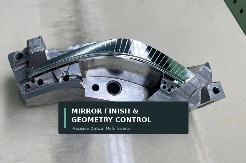
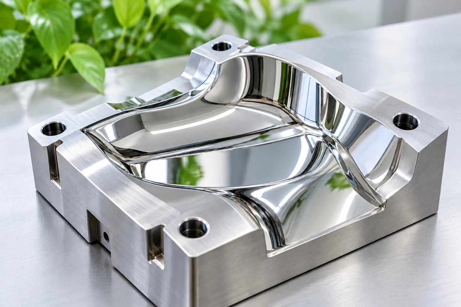
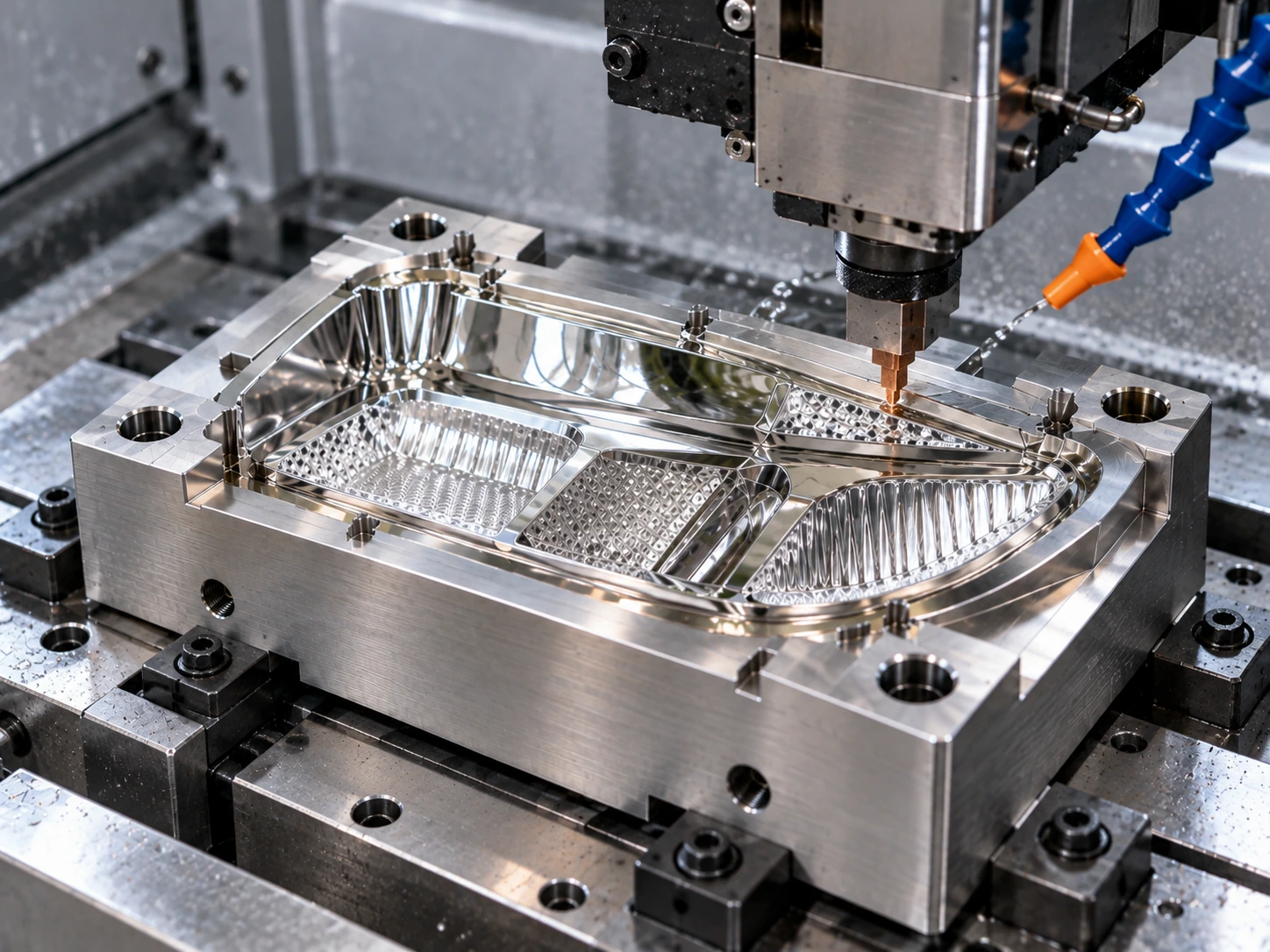
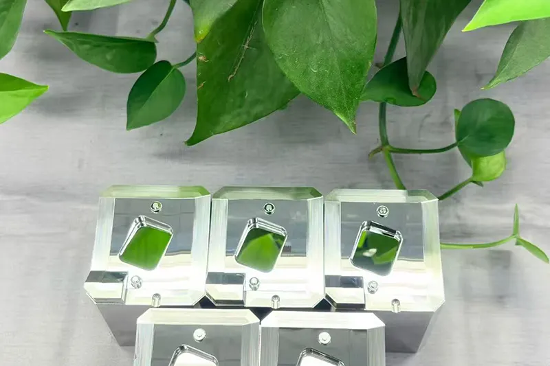
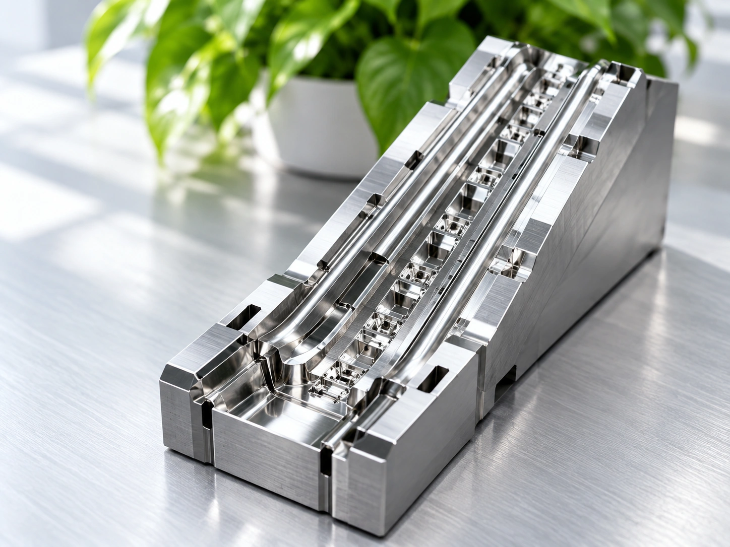
Optical mirror plastic molds demand optical-grade surfaces, commonly requiring surface roughness around Ra below 0.01 µm, or even nanometer level, because the mold finish is transferred directly to every molded part. Getting the mold right is what lets high-volume parts ship without secondary polishing.
Where Roughness Becomes a Purchase Decision
Engineers usually start caring about roughness at the quoting stage, because tighter roughness means more process steps, more metrology, and more risk. The useful question is rarely as smooth as possible but smooth enough for this function, at a workable cost.
Polishing vs Lapping: Which Controls Roughness Better
Lapping and polishing are often used in sequence. Lapping uses two surfaces with abrasive slurry between them and is excellent for flatness and removing stock; polishing uses softer pads with finer abrasive to achieve the mirror finish. In practice, lapping sets the geometry such as flatness and parallelism, while polishing sets the final roughness, so the two processes are complementary rather than interchangeable. Specifying only one usually leaves either the geometry or the finish short of requirements.
Common Materials and Their Roughness Targets
Different substrates reach different floors, and the gap between glass and hard crystals is the part that surprises buyers:
| Substrate | Roughness floor in practice | Notes |
|---|---|---|
| Optical glass, fused silica | Sub-nm Ra, routinely | Easiest to polish to mirror finish |
| Sapphire, silicon carbide, quartz | Low nm Ra with experienced control | Hard, brittle; need careful process development |
| Metals, aluminum, copper, stainless, titanium | Mirror finish achievable | Mirror aluminum and optical mold steels commonly specified very low |
| Plastics, PMMA, PEEK | Achievable, with control | Thermal and creep effects need management |
How Precision Polishing Brings Roughness Down
A typical precision flow starts with lapping to correct geometry, then moves through progressively finer polishing slurries, and ends with a controlled final pass. Shops with multi-axis capability, covering three-axis, five-axis, and six-axis polishing and grinding, can hold the tool normal to complex curved surfaces, which keeps roughness uniform across the part instead of smearing it.
The abrasive progression matters: starting too fine leaves stock and geometry behind, while starting too coarse buries scratches that later polishing cannot remove. Experienced shops sequence grit sizes, control pressure and coolant, and verify between stages so the final pass only removes the last nanometers rather than fighting earlier damage.

Metrology closes the loop: roughness is measured, not assumed. Controlled, repeatable polishing, often robot-assisted, reduces operator variation, which is what lets a supplier hit Ra 1 nm class results consistently rather than by chance. For a deeper look at the process chain, see our optical polishing and lapping services.
How Surface Roughness Is Measured and Verified
You cannot improve what you cannot measure. Common methods include:
- Stylus profilometry: a diamond tip traces the surface; good for Ra and RMS but can mark very soft surfaces.
- Optical interferometry and white-light interferometry: non-contact, maps the surface in 3D, well suited to optical parts.
- Comparison standards: useful on the shop floor but not a substitute for a number on the drawing.
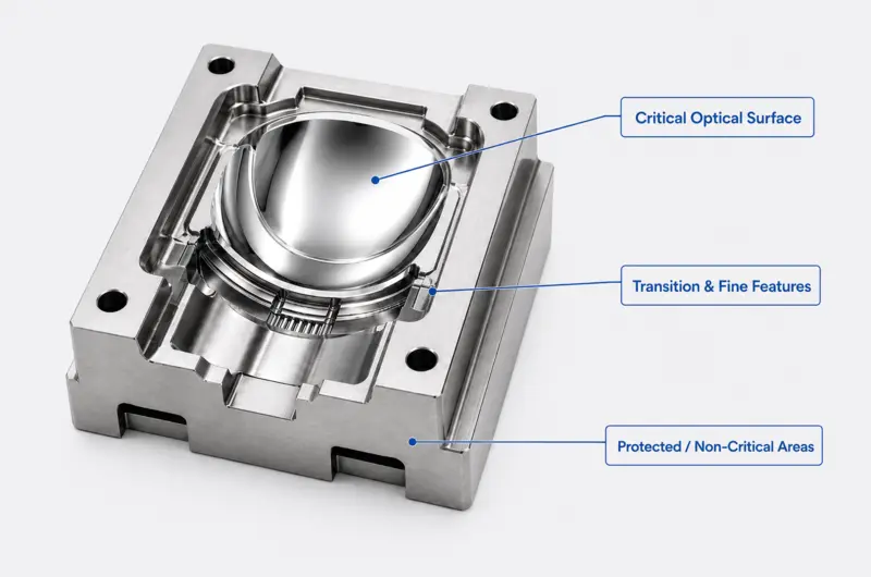
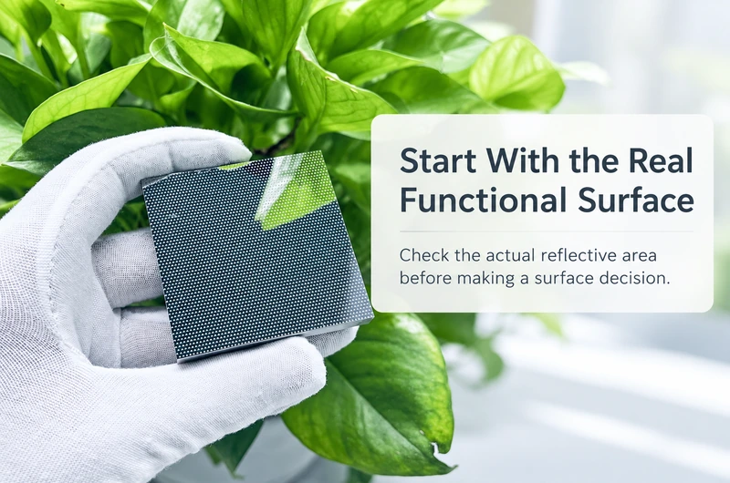
A useful discipline is to mark the critical optical zone, the transition features, and the protected non-critical areas on the drawing, so polishing and inspection focus where performance is won or lost.
Common Surface Roughness Mistakes in Sourcing
- Quoting Ra against RMS: mixing the two parameters without conversion hides a real gap between suppliers.
- Asking for the smoothest possible surface: over-specifying adds cost and lead time with no optical benefit.
- Ignoring the measurement length: Ra depends on the sampled length, so the same part can read differently.
- Forgetting flatness: polishing alone will not fix geometry set by lapping; call out both.
- Treating polish as a final cosmetic step: roughness is a performance parameter, planned from the drawing onward.
Specifying Roughness in a Polishing RFQ
To get an accurate quote and avoid rework, send your supplier:
- Target Ra or RMS, and which one, with the measurement length.
- The functional optical area versus the non-critical area.
- Substrate material and any hardness or brittleness notes.
- Flatness, parallelism, and dimensional tolerance requirements.
- Intended wavelength and any scattering or cosmetic limit.
A drawing that only says polish it will almost always return a part that is either over-processed and expensive or under-spec and rejected; the roughness call-out is what makes the quote meaningful. Suppliers that run precision optical polishing for hard and soft materials typically ask for exactly these inputs before quoting.
Choosing an Optical Polishing Partner
When roughness is on the critical path, evaluate suppliers on more than price:
- Demonstrated process for your material; sapphire, silicon carbide, and quartz are not the same as glass.
- In-house metrology and documented inspection, not just a claim of mirror finish.
- Multi-axis and controlled, robot-assisted polishing for consistency on complex geometry.
- Cleanroom or controlled environment for the final finishing stage.
- Reference experience in your industry, from laser and medical to semiconductor and optics.
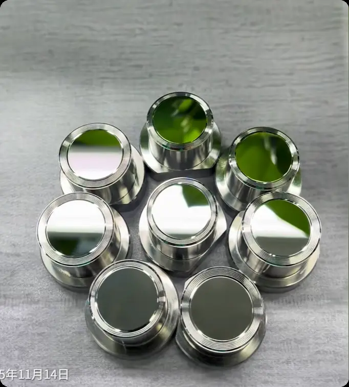
A supplier that can show you the measured roughness on a similar part is worth more than one that simply promises a number. Understanding optical polishing and lapping solutions in depth is what separates a repeatable process from a lucky one.
Frequently Asked Questions
What is a good surface roughness for optical polishing?
It depends on function. Many general optical and mold surfaces are specified around Ra 1 to 10 nm, while imaging and laser parts often call for below Ra 1 nm. There is no single good value; specify against performance.
Is Ra or RMS better for optical parts?
Both are valid if stated. Ra is the more common calling value; RMS weights deep scratches more. Always state which you mean and the measurement length, and convert using RMS roughly 1.1 to 1.25 times Ra when comparing quotes.
Can polishing reach Ra 1 nm on hard materials like sapphire?
It is achievable with the right process and experience, but hard and brittle crystals need careful control of pressure, slurry, and coolant. Expect more process development than for optical glass.
Does lower surface roughness always mean better performance?
Not always. Excessively low roughness can add cost without benefit if the wavelength and application do not require it. The right target is the lowest roughness that meets the optical spec economically.
Why does my polished part still show haze?
Haze usually comes from residual sub-surface damage, contamination, or roughness in the nanometer range combined with embedded slurry. It points to process or cleaning control, not just the final grit size.
How do I write surface roughness on a drawing?
Call out the parameter, Ra or RMS, the value, the cutoff or measurement length, and the zone it applies to. Pair it with flatness and tolerance so the shop knows what to optimize.
Conclusion
Surface roughness is not a finishing afterthought; it is a performance parameter that shapes transmission, reflection, scattering, and ultimately whether an optical product works. Specifying it correctly, and working with a polishing partner that can measure and hold it, protects both performance and budget.
If your next component lives or dies on its surface, review YISHUN Optical’s optical polishing and lapping services or explore the full range of YISHUN Optical’s precision manufacturing capabilities to discuss a spec-driven quote.